MCS to FHS
The interface from the MCS to the FHS is largely in the form of communication between Tango devices running on either side.
Command Sequence
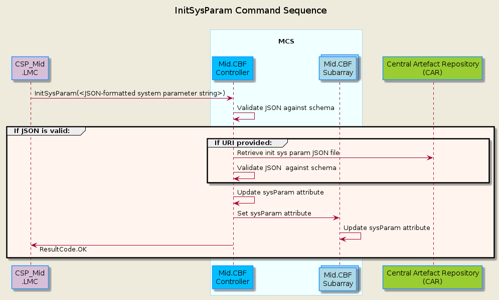
InitSysParam Sequence
The sequence diagram below shows the main sequence of calls in MCS to initialize the system parameters.
AssignResources Sequence
The sequence diagram below shows the main sequence of calls in MCS to assign dish resources to a subarray.
![@startuml
'https://plantuml.com/sequence-diagram
skinparam backgroundColor #EEEBDC
skinparam sequence {
ParticipantBorderColor DodgerBlue
ParticipantBackgroundColor DeepSkyBlue
ActorBorderColor DarkGreen
ActorBackgroundColor Green
BoxBorderColor LightBlue
BoxBackgroundColor #F0FFFF
}
skinparam collections {
BackGroundColor LightBlue
BorderColor DodgerBlue
}
title MCS Correlation Assign Resources\n
participant "TMC\n" as tmc #Gold
participant "CSP_Mid\n.LMC" as lmc #Thistle
box "\nMCS\n"
participant "Mid.CBF\nSubarray" as subarray
end box
box "\nFHS\n"
collections "VCC All Bands\n" as vcc
end box
note over subarray : ObsState: EMPTY
lmc -> subarray : AssignResources(list[str])
note over subarray : ObsState: RESOURCING
subarray -> subarray : Validate receptors in argin
group #SeaShell If len(valid receptors) > 0:
group #LightCyan For each receptor:
subarray -> vcc : UpdateSubarrayMembership(int)
note over vcc : Add Subarray to \nSubarrayMembership
subarray <-- vcc : Success or Failed
end group
alt At least one VCC All Bands return Success
subarray -> subarray : Update dishIDs assigned
note over subarray : ObsState: IDLE
lmc <-- subarray : Success
else Failure in AssignResources, ObsState unchanged
note over subarray : ObsState: EMPTY
lmc <-- subarray : Failed
end group
@enduml](../../_images/plantuml-740fe29d9cb4a76e925d93138371555b0de9d6e9.png)
ReleaseResources Sequence
The sequence diagram below shows the main sequence of calls in MCS to release dish resources from a subarray.
Note: the RemoveAllReceptors command has the same code flow, the only difference being that it takes in no argument and instead releases all assigned dish resources.
![@startuml
'https://plantuml.com/sequence-diagram
skinparam backgroundColor #EEEBDC
skinparam sequence {
ParticipantBorderColor DodgerBlue
ParticipantBackgroundColor DeepSkyBlue
ActorBorderColor DarkGreen
ActorBackgroundColor Green
BoxBorderColor LightBlue
BoxBackgroundColor #F0FFFF
}
skinparam collections {
BackGroundColor LightBlue
BorderColor DodgerBlue
}
title MCS Correlation Release Resources\n
participant "TMC\n" as tmc #Gold
participant "CSP_Mid\n.LMC" as lmc #Thistle
box "\nMCS\n"
participant "Mid.CBF\nSubarray" as subarray
end box
box "\nFHS\n"
collections "VCC All Bands\n" as vcc
end box
lmc -> subarray : ReleaseResources(list[str])
note over subarray : ObsState: RESOURCING
subarray -> subarray : Validate receptors in\nargin were assigned
group #LightCyan For each receptor in argin:
subarray -> vcc : UpdateSubarrayMembership(0)
note over vcc : Clear out Subarray Memebership
subarray <-- vcc : Success or Failed
end group
alt #SeaShell Failed to release all receptors
note over subarray : ObsState: IDLE
lmc <-- subarray : Failed
else #SeaShell All receptors were successfully released
subarray -> subarray : Unsubscribe events from\nreleased receptors
subarray -> subarray : Update receptors
note over subarray : ObsState: EMPTY
lmc <-- subarray : Success
end group
@enduml](../../_images/plantuml-b6720988f235e05e1e5a29bd23429283bd530e57.png)
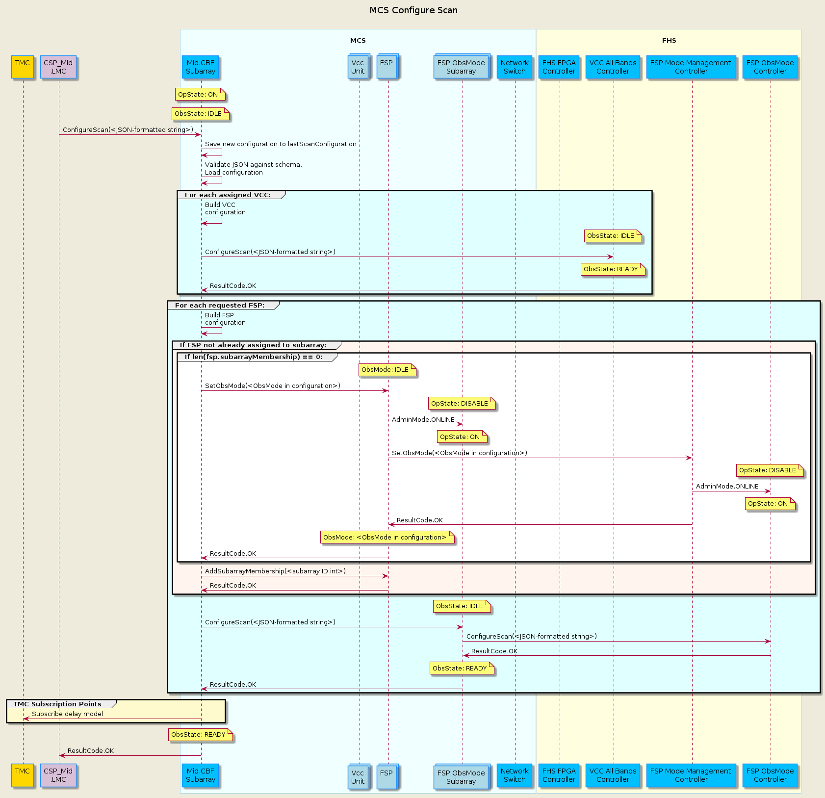
Configure Scan Sequence
MCS currently supports Correlation observing mode. All modes have their own specific schema for the ConfigureScan input JSON-formatted string.
All Observing Modes
The sequence diagram below shows the main sequence of calls in MCS to configure a scan.
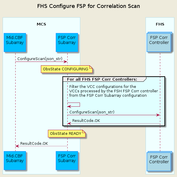
Correlation (CORR)
The sequence diagram below shows details of calls to configure a FSP for a CORR scan.
Pulsar Search Timing (PST)
(Currently not implemented)
TODO
The sequence diagram below shows details of calls to configure a FSP for a PST scan.
Abort Sequence
(Currently not implemented)
TODO
The sequence diagram below shows the main sequence of calls in MCS to Abort from a correlation/pst scan. Return calls are not shown.
ObsReset Sequence
(Currently not implemented)
TODO
The sequence diagram below shows the main sequence of calls in MCS to return to IDLE via the ObsReset command for a correlation/pst scan. Return calls are not shown.
Restart Sequence
(Currently not implemented)
TODO
The sequence diagram below shows the main sequence of calls in MCS to return to EMPTY via the Restart command for a correlation/pst scan. Return calls are not shown.
Synchronizing HBM Corner Turner Initial Write Timestamp
The initial write timestamp values published by all the High Bandwidth Memory (HBM) Corner Turner FHS devices will be captured by the MCS FSP Tango device. In turn, once it has received the first initial write timestamp value, the MCS device will propagate it back down to the FHS FSP devices to synchronize the corner turners across all FPGAs in the FSP Unit, ensuring all outputs by all FSP Unit FPGAs are aligned to generate with the same initial timestamp.
This synchronization procedure must occur every time the FSP Unit transitions from having no input data from any VCCs to having at least one active input signal from one VCC.
The overall behaviour of the Corner Turners (CT) is as follows:
Expected operation of the corner turners is that once at least 1 VCC has data flowing, then all FGPAs will have data flowing; normal operation is that as long as at least 1 VCC continues to send data to the FSP, all corner turners will get data (it could be different VCCs from different scans) and no re-initialization is required
Data will stop flowing when all VCCs stop sending data. Once data starts flowing again as above, all corner turners need to be re-initialized
MCS Sequence for Initializing the Corner Turners:
When FSP receives the command SetObsMode
If the obs mode is changing from IDLE to CORR, the FSP subscribes to the first_write_timestamp on every FHS FSP CORR Controller (x8)
If the obs mode is changing from CORR to IDLE the FSP unsubscribes to the first_write_timestamp on every FHS FSP CORR Controller (x8)
MCS receives change events for first_write_timestamp and uses the first such event to start the initialization process (MCS does not wait for an event from each FPGA).
Once MCS detects that the CTs need to be initialized, a configure corner turner command is sent containing
first_read_timestamp
MCS will set first_read_timestamp to be first_write_timestamp; any adjustments to the first_write_timestamp (such as adding the read_threshold to reduce the amount of flagged data going to SDP) will be done in the FHS FSP top level controller
If MCS encounters DevFailed error while trying to Configure a specific FHS FSP Corr’s Corner Turner, MCS will attempt to retry configuring the Corner Turner 2 more times using the same initial timestamp given in the initial configuration attempt.
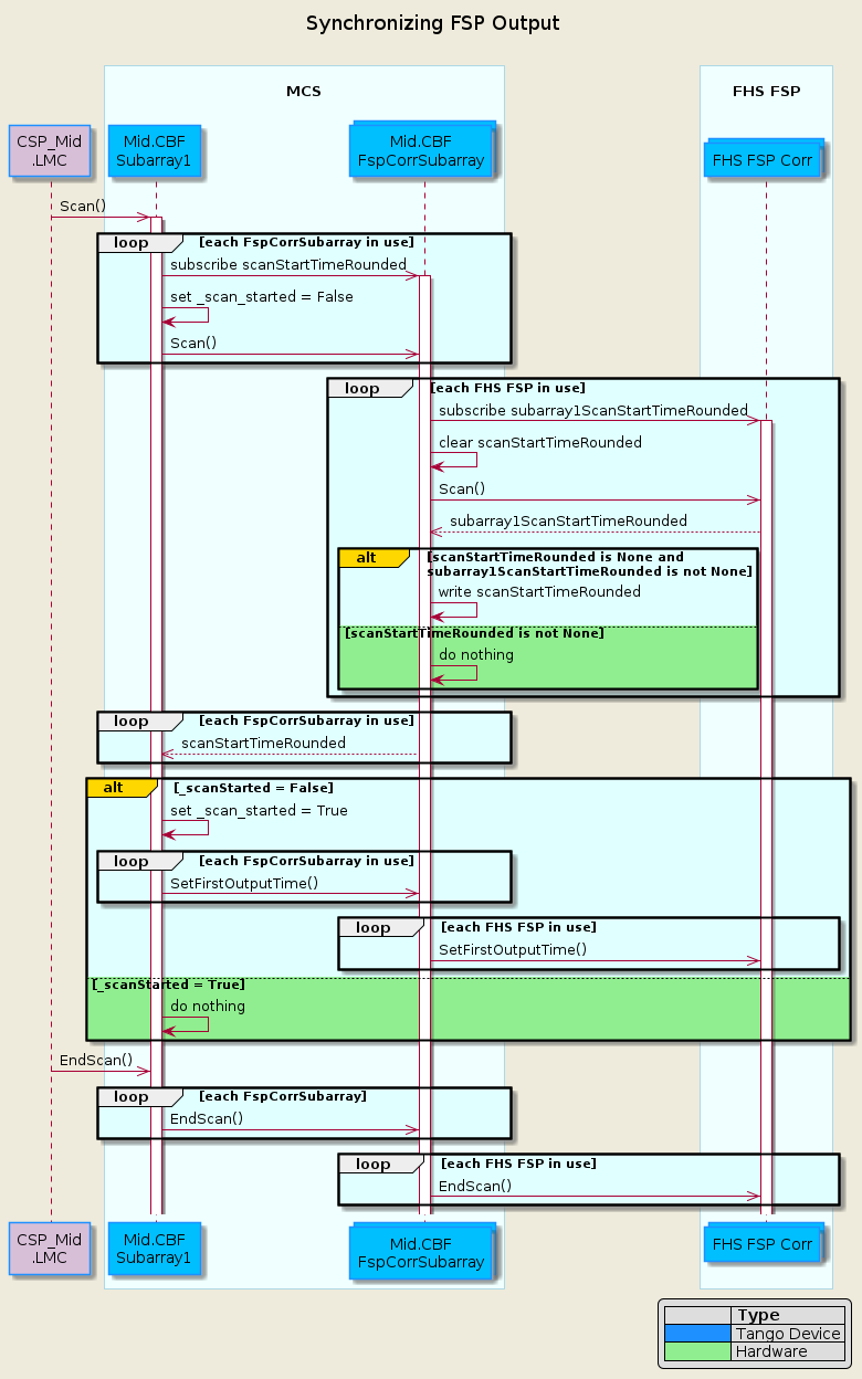
Synchronizing FSP Output Time Sequence
Every FSP producing output for a Subarray must have the same time to start producing products. The FHS FSP software will use the first output time to drop data received before this time.
The Mid.CBF Subarray will coordinate the first output time across all FSPs that the Subarray is using for a scan. This first output time will be based on the time the data started flowing for the scan, as determined and provided by the FHS FSP Corr top level controller.
For correlation, each Mid.CBF Subarray communicates with a single FSPCorrSubarray Tango device for each FSP that it is using for the scan. Each FSPCorrSubarray Tango device communicates with up to 8 FHS FSP top level controllers. In this design, this communication hierarchy is maintained.
The sequence diagram below shows the sequence of calls in MCS to synchronize the FSP Output Time for Subarray 1.
subarray1ScanStartTime is one of 16 subarray<1-16>ScanStartTime attributes found in FHS FSP Corr that corresponds to one of the 16 Subarray that can be assigned to FHS FSP Corr. MCS FSPCorrSubarray subscribes the FHS FSP Corr subarray<1-16>ScanStartTime that corresponds to the FSPCorrSubarray’s assigned Subarray.